
Today we will be making a color loop using LEDs. This is an easy arduino project that is great for beginners.
What you will need
To start with, the basic parts you will need include:
-
1 Arduino uno with a USB cable
-
1 Breadboard
-
4 LEDS
-
4 200 ohm resistors
-
8 Jumper cables
In addition, you may want to install the Arduino IDE, if you haven’t already, to help upload your programs to the arduino board. Before any wiring is done, I design and prototype the circuitry using Tinkercad, an online tool that lets you create models, write their code and test them out. This saves me a bunch of time when it comes to the actual wiring process.
Putting it all together
We shall be connecting the parts as shown in the image below:

We will use the arduino pins labeled GND, 13, 12, 11 and 10 on the arduino.
Place the LED’s and resistors on the breadboard
We will use a breadboard to connect all our LED’s and resistors. If you haven’t used a breadboard before worry not. I will not go into the intricate details of how they work in this post, but with basic information you can get the gist of how to use certain areas for wiring. The most basic thing you need to know about breadboards is that, components placed on a row are connected to each other. To connect parts on different rows, you must connect a wire between the rows.(You can find more detailed info about how breadboards work in the links below).
We will be placing each LED in series with a resistor, then wiring each LED resistor pair in parallel to each other.
Our first connection is one LED and one resistor.
LED’s typically have one leg longer than the other. The longer leg is the anode(positive side) while the shorter leg is the cathode(negative side). You can bend the longer leg until both the legs are equal in length. The bent leg is now easily distinguishable as the positive side of the diode.
Place the negative side of the LED on one row and the positive on the next row. Place one end(any end) of the resistor on the same row as the positive side of the LED and the other end into a slot in any free row.

Repeat for the rest of the LEDs and resistors until you have something similar to the configuration below:


Wire all the parts together
Now that we have placed our LED’s and resistors on the board, we can move on to the wiring phase. We shall be connecting a wire from each pin to the negative side of the LED.
Connect a wire from the GND(Ground) pin to the LED row that has the negative side. (Note, in my configuration the positive and negative ends of the LEDs are placed on separate rows. If you are following a different configuration where both LED ends are on the same row, place the end of the cable on the pin closest to the negative side of the LED.)
Next, connect a second cable from pin13 to the row with the end of the first resistor. (Note, in my configuration the end of the second resistor is on the same row as the start of the second LED according to our breadboard. If you place these on separate rows, you will need a cable to join these two rows together)

Then connect a third cable from pin12 to the row with the end of the second resistor.

Repeat this with pin11 and pin10, until the final wiring configuration is shown:

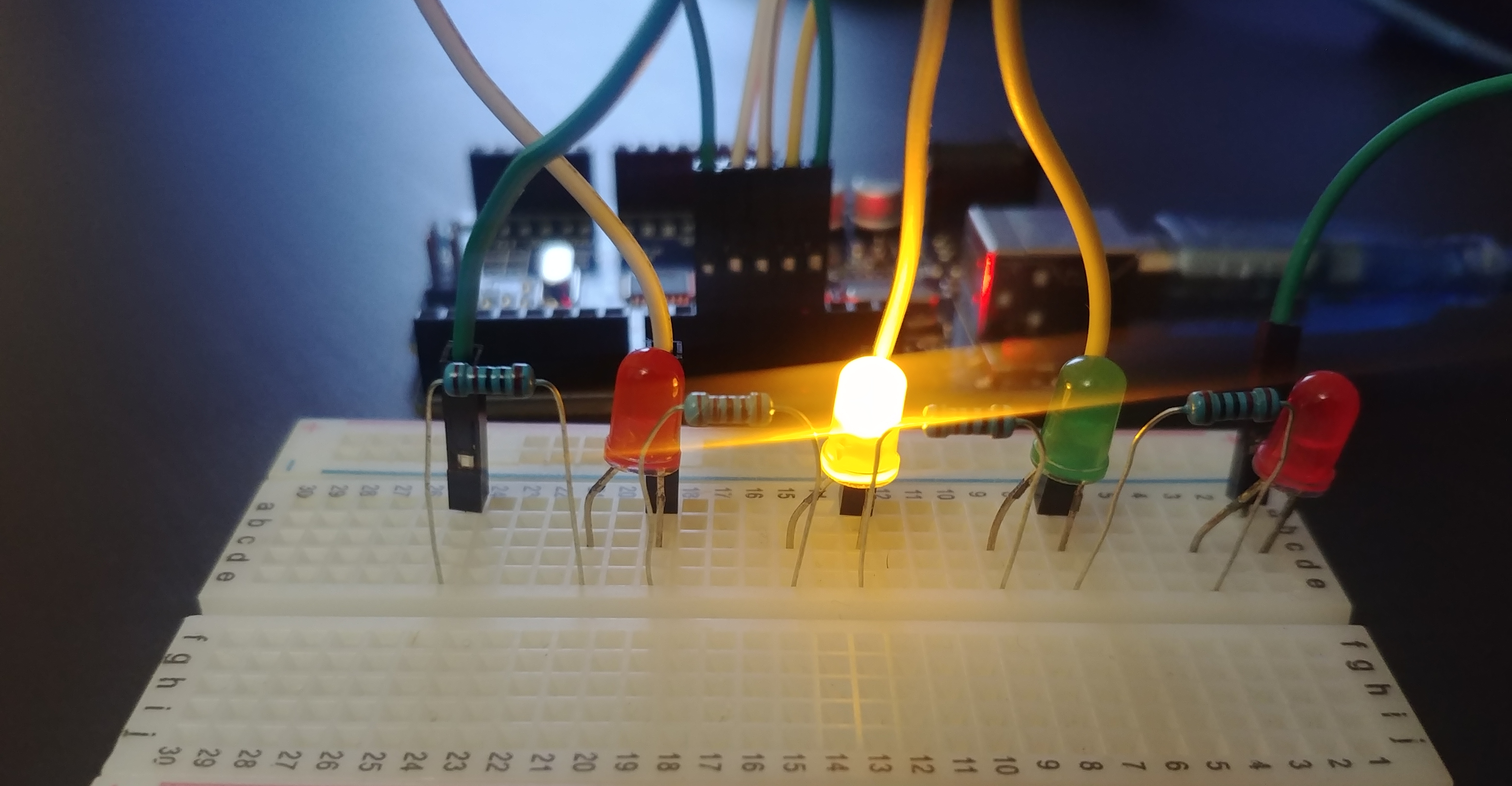
Your actual wiring should look somewhat similar to the wiring shown below:

Now it’s time to write the program.
Writing and running the program
For this we will need the Arduino IDE. I am hoping you managed to install it with no problem. If you haven’t installed it by now, you can refer to this link: Installing Arduino IDE.
We want the LED’s to be lit in a sequence from the first LED to the last and then start all over again, running in a loop.
Generally, we shall do this by first assigning our arduino pins that connect to the LED’s as output pins. Once this is done, we will loop between lighting one LED, having a short delay, then lighting another LED till we reach the last LED. This will then cycle back to the first LED repeating the process in a loop.
Launch your Arduino IDE and open a new file. We will start by running a test for just 1 LED. Save your file name as LED_bulb_test. Write the code below inside the editor and save.
void setup() {
  // put your setup code here, to run once:
  pinMode(13, OUTPUT);
}

void loop() {
  // put your main code here, to run repeatedly:
  digitalWrite(13, HIGH);
  delay(1000); // Wait for 1000 millisecond(s)
  digitalWrite(13, LOW);
  delay(1000); // Wait for 1000 millisecond(s)
}
Once done, connect your Arduino via the USB port and run the program. Running the program uploads the code to the Arduino board. (Note: Once programs are uploaded to the board, they remain on the board until another program is uploaded to overwrite the existing program.)
The LED connected to output pin 13 lights up then goes off after every second, running consistently in a loop inside the loop function.
We will then modify the above program to run for our 4 LED bulbs. Create a new file and call it LED_color_loop. Our modified program will first select the output pins, then in a loop alternate lighting up one after the other for every second.
int count = 4;
int leds[] = {13, 12, 11, 10};
int state[] = {HIGH, LOW, LOW, LOW};
int currentHighLed = 0;

void setup(){
  for (int i = 0; i < count; i++) {
    pinMode(leds[i], OUTPUT);
  }
}

void loop(){
  for (int i = 0; i < count; i++) {
    digitalWrite(leds[i], state[i]);
  }
  state[currentHighLed] = LOW;
  currentHighLed ++;
  if (currentHighLed >= count) {
    currentHighLed = 0;
  }
  state[currentHighLed] = HIGH;
  delay(1000);
}
Save and run the program. Your LED’s should light up as shown below:

Great job! Hopefully seeing your work gives you a taste of what you can do with your Arduino.